switched mode power supply version 1.0
High-Amp mobilises you! On this side you find a description how to build a switched mode power supply for the transistor amplifier to supply it with a 12V voltage source. The power supply delivers stabilized +/-350V, 15V and an additional abitrary voltage to supply a walkman, discman, mp3 player etc.
circuit
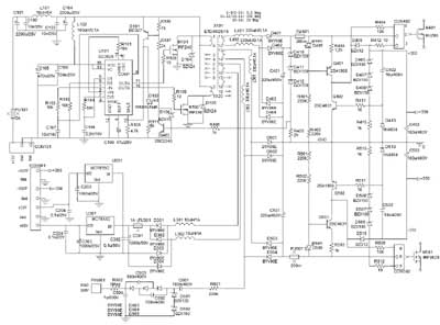 |
Main item of the circuit is the switch mode controller SG3525. It is designed to drive the transformer, working in push pull topology, symmetrically. The two primary windings of the transformer X101 are alternately switched by MOSFETs to ground. This has the same effect as connecting one primary winding of a transformer to an AC voltage where Vss=2Ub. The two MOSFETs are driven by the pins OUTA and OUTB of U101. The switching frequenzy is 35KHz, determined by R103 and C108. To prefent overlapping of On-Time of the MOSFETs a dead time is determined by R104. C109 configures a soft start behavior to prefent current peaks at startup. Switching inductances means the occurance of transients. L101, C101-C104 works as a transient killer to surpress transients on the 12V power line. L102 ensures a free of transient supply for U101. To prefent the parts, connected on the secondary side of the transformer from overvoltage, the circuit has a protection circuit included. If the voltag at C401 will exceed the summ of the zener voltages of D410 - D412, Q403 will open and in consequence Q101. +Ub at pin10 of U101 will shutdown OUTA and OUTB. If the input voltage will exceed 17V, D106 will open Q101 and shutdown OUTA and OUTB completely to prefent the gates of the MOSFETs from overvoltage.
On the secondary side you find a familiar pattern. The circuit for the stabilized +/-350V is taken from the regulated power supply and is described there in detail. The diodes BYV96E are very fast and can be used to rectify the high frequency AC-voltage from the transformer. Because of the high switching frequency you can dial down the values of the capacitors of the cascade considerable.
The crunch of this design is the transformer. One cannot help but notice to build it by yourself. As core I chose a ETD49/25/16 N87. Oversized regarding the power but provides space enough for the high number of windings on the secondary side. Here are some hints that you should follow when you want to succeed this intention:
Start with the primary windings. Use two parts enamelled copper wire 1,1mm², 1meter long each part. Connect one end of the first wire to pin 1 and one end of the second wire to pin 2 and wound them parallel and tightly on the coil bobbin. After 9,5 windings lead them parallel back to pin 9/10. A wire thickness of 1,1mm² will fill exactly one layer of a ETD49.
Place an isolation layer on the primary layer.
The secondary windings are to be wound with 0,1mm² enemalled copper wire. Begin with the first 320 windings, followed by the next 320 windings, last 20 windings with 0,5mm² wire.
One layer must be wound along the complete width of the coil bobbin to ensure a maximum magnetic coupling.
After each layer and between the three secondary windings place an isolation layer between. Use shrink tubbing to isolate the wires you lead back to the pins.
As isolation layers I used oven bags from TOPPITS. They are very thin and isolating, heat resistand up to 200° C and are comfortable to handle. In order to electromagnetic isolate the transformer, place it into a sheet-metal case, especially when the transformer is close to the amplifier.
layout
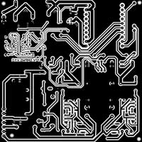
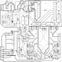
dimension: 160 x 160 mm
partlist download here.
Sprint-Layout-file can be downloaded here.
starting up
WARNING!!!
Remember that you are handling with high voltages that can be dangerous to life. So if you are working on powerd on devices use only one hand in order to prevent electrical shock.
The starting up should be done step by step. Initially connect the circuit to 12V without transformer.
If the squarewave signals to drive the MOSFETs are proper add the transformer to the board.
Now power on the circuit without all secondary fuses. The input current should not increase 0,3A. Check the secondary voltages at the ELKOs: 2x400V and 30V.
To test the protection circuit, increase the input voltage until the voltage at C401 reaches 450V. The squarewaves to drive the MOSFETs should be reduced to short peaks.
Now increase the input voltage to more than 17V. The driving voltage of the MOSFETs should stop completely.
Now add all fuses to the board and check the stabilized voltages.
At last check the power supply with the intended load (amplifier).
result
The supply works with an input voltage range from 12 - 15V to ensure the stabalized +/-350V output voltage. The demanded current of 40mA for the transistor amplifier are supplied without any problems, the maximum current that can be supplied is significantly higher. The combination of encapsulating the transformer into a sheet-metal case and LC-filtering will eliminate transients on the power rails very effectively. This results to excellent audiophil characteristics of the connected amplifier. Compared to my transistor amplifier with conventionally power supply, for me there is no difference in sound to discover.
The costs for this project will amount to about 120 Euro.