regulated power supply version 2
I want to introduce alternatively a power supply with regulated output voltage. It is designed to drive all amplifieres shown here on these sites, and has also included the two auxiliary voltages that are used for the Canopus and the Capella. It features low impedance outputs and very low ripple. By comparison to my first version it has a ten times lower output impedance.
circuit
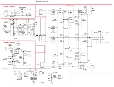 |
The constant current source Q401 draws 1mA, determined by R403. Q401 supplies the gate of the output MOSFET with a voltage of 400Volt + VGS. If the output voltage rises the sum of the zener voltages D406 to D408 + UBE, Q402 will open and reduce the gate voltage of the output MOSFET. So the feedback loop is closed. D409 will protect the gate of the MOSFET against over voltage and wrong polarity. The output ELKO C403 will prevent oscillation and keeps the output voltage absolutly quiet. The circuit for the 150Volt auxiliary voltage works similar, however the reference voltage is generated at the emitter of Q701.
To generate the negative supply voltage I used the IRF9620 as output MOSFET. It can only 200Volt but in normal operation if the difference of input voltage - output voltage is less than 200Volt it is no problem. Only in start up, if the output voltage is still down, the voltage can exceed 200Volt. In this case the integrated overvoltage protection will protect the device against being damaged. So if you replace the IRF9620 be sure that it has a overvoltage protection included. Or use the FQP3P50 from Fairchild, it’s a 500V type.
The delay circuit is only used to drive amplifiers with tubes included, else you have to bridge the contact pins of the relais. It is realized by the universal timer IC 555C. The delay time can be adjusted by R302 to 20 seconds. If you supply the delay circuit with 6,3V DC, then bridge D301 and R305 to ensure that 6V will arrive at the relais.
Layout
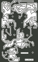
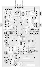
dimension: 106 x 173 mm
Partlist download here.
starting up
WARNING!!!
Remember that you are handling with high voltages that can be dangerous to life. So if you are working on powerd on devices use only one hand in order to prevent electrical shock.
The power supply is designed for best sound, not for best reliability. If you are starting up with the power supply be very carefull and avoid short-circuits. Once you have powered on the supply be shure that all Elkos are discharged before going on working at it. Even a charge of 50V on an Elko can destroy several Elkos if you make any short-circuit with a screw driver or the soldering iron. Once the power supply works and is connected proper to the amplifier it will work fine, maybe to the end of time.
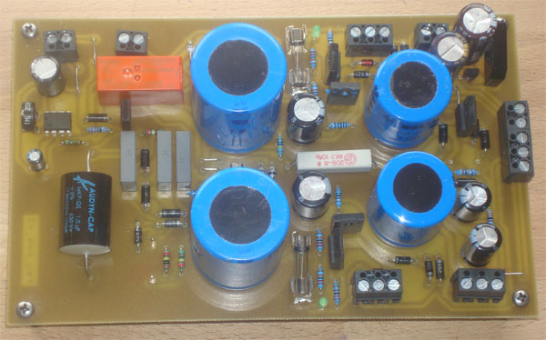
result
The output voltages of the main supply are determinded by the sum of the zener voltages D406 to D408 and can be defined in a wide range. The output impedance of the main supply and the auxiliary voltage 1 is < 0,2ohm over a frequency range from 0 to 100KHz, ripple is no longer measurable.
I have already done some extended tests with my transistoramp. The bass sounds deeper and more structured. The reproduction of impulses has improved too, all in all the amplifier sounds more clear and transparent.
regulated power supply (first draft)
regulated powersupply
with softstart for tube filament
In order to minimize hum and noise of a tube amp, induced by the heater supply, it is recommended to use a stabilized 6,3 Volt powersupply. The suggestet circuit described here works with a 9 - 10 Volt AC input voltage and supplies a stabilized DC output voltage, adjustable between 2,85 and 8,6 Volt. A integrated softstart function raises up the output voltage after power on in a predefined time from 0,45 volt to the calibrated output voltage.
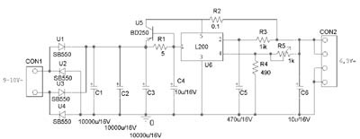 |
The core of this circuit is the adjustable voltage and current regulator L200. In order to increase the internal current limit of 2 Ampere I used a BD250 for delivering a higher output current. When the voltage drop of 0,6 Volt over R1 is reached, U5 beginns to supply the additional current for the output. R2 is optional and can be used as an external current limit (Imax = 0,45V/R2) = 4,5 Ampere. The output voltage is adjusted by R5. R3 and C5 determine the steepness of the slew rate after power on. The schottky diodes SB550 I used to rectify the AC-voltage are limited to 5 Ampere, the maximum load without external current limit is 7 Ampere.
Layout
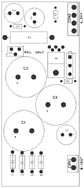
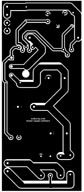
dimension: 50 x 118 mm
Partlist download here.
electronic fuse
Because of the bad experience I made with fuses (standard fuse sounds terrible, PADIS fuse is expensive) I developed a little circuit to protect the electrical parts in the amplifier without having negativ influence on sound.

In normal operation T3 gets the gate source voltage from R12 and is turned on. If the current through T3 exceeds a limit which is determined by R13, D21 beginns to open and T4 beginns to turn on. The gate voltage at T3 is reduced and limits the current through T3. Now the voltage across T3 is increasing. If it reaches the zener voltage of D22, a current across R15 and D20 beginns to flow and turns on T4 completely. The gate voltage is reduced to 0 and T3 is turned of. T3 will turn on again when the voltage across drain to source has fallen below the zener voltage of D22. At R13=10 Ohm the current is limited to about 70mA. C7 is used to delay the total shutdown.
Advantage of the electrical fuse:
- the maximum current is at no time higher than the adjusted value
- In case of a short cut the current will be limited to about 3 mA
- no negative influence in sound
Disadvantages
- increased effort by placing components
- voltage drop of about 5V in normal operation
The circuit fits on a 20x20mm board which can be soldered at a burned fuse. So the fuse on the pws can be replaced without problems.


Layout, schematics etc. can be downloaded here.