|
Hybridamp Canopus (RTR400)
circuit |
|
|
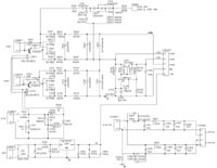
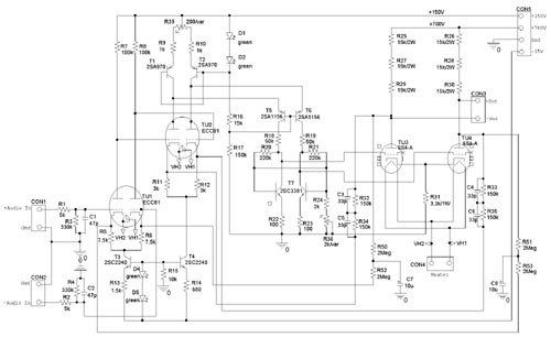
Strictly speaking this design is a tubeamplifier because the complete voltage gain is made by tubes. T5 and T6 don't have any voltage gain and are simply used to bottom down the signal voltage back to ground which was shifted up by the input stages. All other transistors are acting as constant current source. Like the other designs it's a balanced DC-coupled Class-A amplifier. The input signal meets the input differential amplifier TU1. The gain of this stage is defined by the quotient of 100K/7,5K, reduced to 10 by the low transconductance of the tube. The signal is taken directly from the anode of TU1 and meets the input of the next differential amplifier TU2. The anodes of these tubes are supplied by constant current sources T1 and T2. That way the signal current, generatetd by TU2 is blocked by T1and T2 and has to pass T5 and T6. The signal current will generate a voltage drop over R20/R21 and is taken to drive the gates of the output tubes. The working principle of T7 you already know from the schematics of the hybridamp. It works as current source that supplies a constant DC-BIAS for the output tubes and blocks the audio signal by delivering a high output impedance for a maximum gain of the signal. The gain of this stage is 220K/3K, reduced to 50 by the low transconductance of the tube. With a load of 45K for the output tubes you have a gain of about 14 for the last stage, the BIAS current for the output tubes is 8mA. Remember that you are working with unbalanced power supply, that means at CON3 is a BIAS voltage of Ub/2 present. To prevent oszillation, I did not use an overall feedback. Instead I used four 150K resistors to feed back the output signal on the kathodes of TU2 to reduce the gain of stage 2 and 3 to 100. Together with the first stage the gain of the amplifier is 1000. The 33p capacitors in the feedback circuit are used to keep the amp stable. In order to reduce voltage drift there is a DC feedback included, consisting of four 2Meg resistors and two 10u capacitors. Frequencies under 0,02 Hz are handled with an amplification factor of 300.
In order to reduce hum I use a DC-supply for filament. Depending of the input impedance you have to fit in R401/402 to receive the desired filament voltage of 6,3 Volt.
|
|
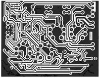
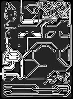
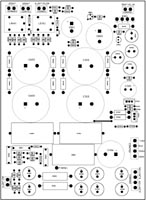
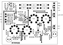
Layout |
||||||||
 |
 |
|||||||
 |
||||||||
 |
||||||||
|
|
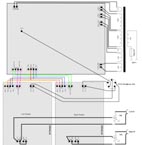
Here my designs for front- and backplane for the Frontplatten-Designer from schaeffer-apparatebau. |
|
starting up
WARNING!!! Remember that you are handling with high voltages that can be dangerous to life. So if you are working on powerd on devices use only one hand in order to prevent electrical shock.
If the amplifier is connected to the power supply you can begin with adjustment. Connect the input to ground and adjust the output voltage at +Out to +350 Volt using R36. Now use R39 to adjust the voltage between +Out and -Out to zero. Repeat this procedure until there is no longer a difference to measure. The amplifier is now adjusted and ready for operation. Remember that BIAS tends to drift away if using virgin tubes, so adjust the amplifier again after 10 hours ontime.
result
With a supply voltage of 700 Volt the amplifier can output 350 Volt eff. if you increase the power supply to a maximum of 800 Volt it can output up to 400 Volt eff (=1100Volt Vss from stator to stator). The 6S4-A can withstand 2KV peaks and has a maximum power consumption of 8,5W so it will operate within proper limits. The power consumption of the amplifier is 70 Watt. It can drive all STAX Pro headphones (580Volt BIAS), if you reduce BIAS to 280Volt it can drive all STAX headphones. Certainly you can drive other electrostatic headphones like KOSS, Sennheiser, etc, just fit the BIAS to the desired value. The amplifier sounds very near to my Alpha Centauri V1.0. Incisive is the fine resolution in the high frequencies and altogether it sounds a little bit more like a tubeamp.
measurement results (supply voltage 800Volt, all voltages RMS) distortion level vs. output voltage f=1KHz: 100Volt: 0,02% distortion level vs. frequency: Uout = 100Volt: 100Hz: 0,025 Uout = 200Volt: 100Hz: 0,05% chanel seperation vs. frequency (Uout = 100Volt): 100Hz: >90dB signal-to-noise ratio: 90dB output impedance at 1KHz: 2KOhm frequency response (-3dB): 0,02 - 50000 Hz
|