regulated power supply version 5.0
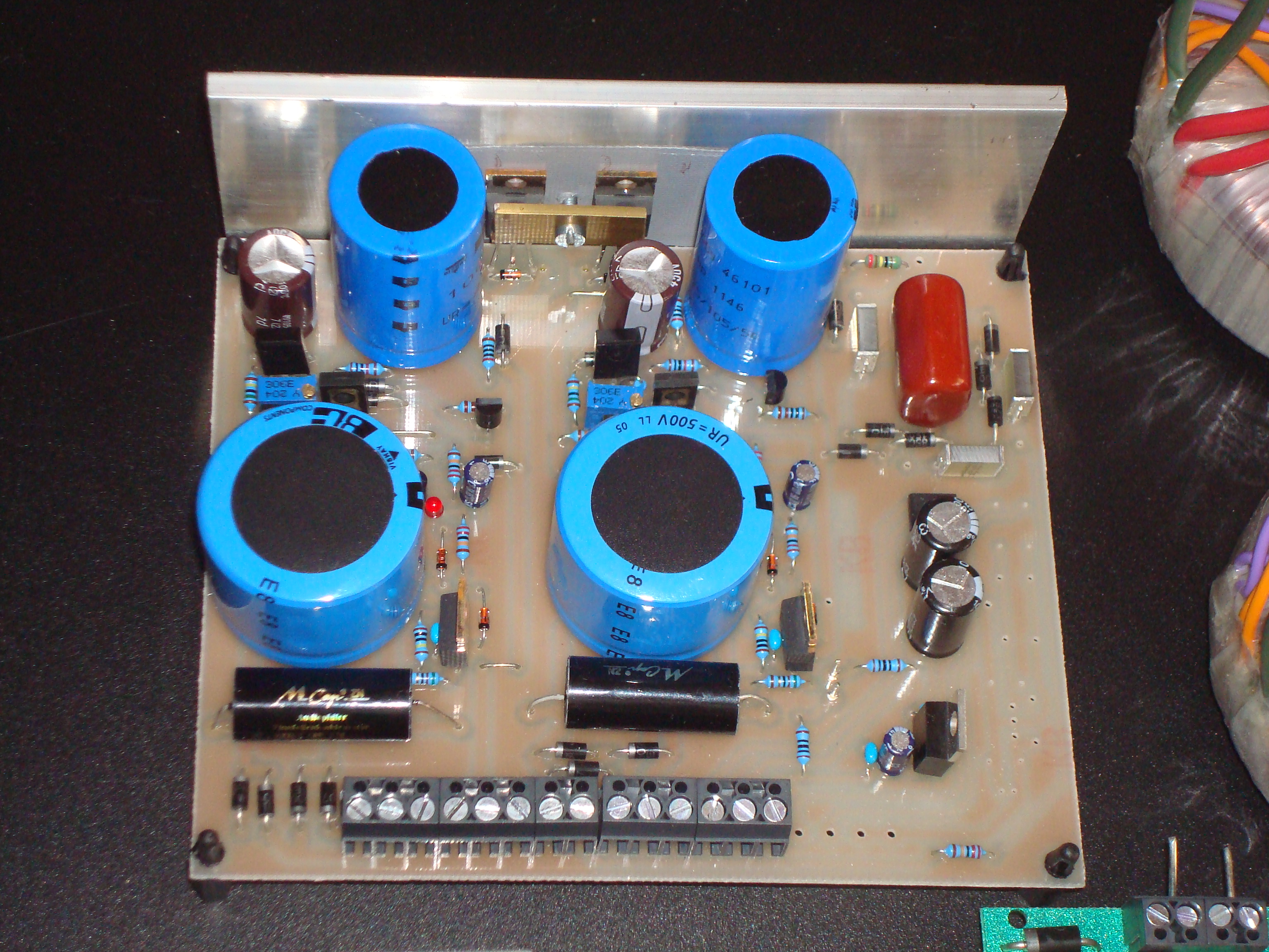
Alternatively I want to introduce an additional power supply with regulated output voltage, especially for the Sirius and Alpha Centauri amplifiers. It features low impedance outputs and very low ripple. By comparison to the first version it has a ten times lower output impedance. Additionaly a tailor-made electronical fuse replaces the conventional fuse for a better protection against short-circuit, without having negativ influence on sound. In this version the main supply is generated by cascading two +400V sources to +/-400V. It reduces the amount of different semiconductors. The applied cascode circuit in the feedback loop allows the application of semiconductors with more suitable parameters (faster, lower noise) which improve the dynamic behavior of the circuit.
For the Alpha Centauri you find an add-on below, containing the delay circuit for the main supply and the regulator for the heater voltage.
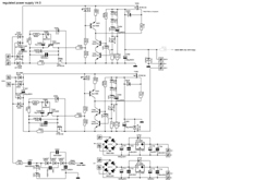
circuit

The constant current source T403 draws 2mA, determined by R407. T404 supplies the gate of the output MOSFET with a voltage of 400Volt + VGS. If the output voltage rises above the voltage of the, I call it adjustable zener diode, consisting of R412,R413, R415, T406 D411, T405 will open and reduce the gate voltage of the output MOSFET. So the feedback loop is closed. D413 supplies the bias for the cascode circuit T404, T405. D414, D415, D416, D417 are protection diodes against overvoltage or wrong porarity. The output ELKO C405 will prevent oscillation and keeps the output voltage absolutly quiet. C404 causes the output voltage to rise slowly at startup and offers a low impedance feedback for voltage fluctuations.
The circuit around T401 works as electronical fuse. In normal operation T401 gets the gate source voltage from R404, R405 and is turned on. If the current through T401 exceeds a limit which is determined by R403, the gate-source-voltage of T401 is reduced and limits the current. Now the voltage across T401 is increasing. If it reaches the zener voltage of D405, a current across R402 and D406 begins to flow and turns on T402. T401 is now turned of completely. T401 will turn on again when the voltage across drain-source has fallen below the zener voltage of D405. At R403=51 Ohm the current is limited to about 120mA. C402 determines how long the maximum current can flow until total shutdown. Because of a very high dV/dt at the drain of T401 the gate must be protected by a 100nF capacitor C403 to divert the current coming from the paracitic drain-gate-capacitor at total shutdown.
starting up
WARNING!!!
Remember that you are handling with high voltages that can be dangerous to life. So if you are working on powerd on devices use only one hand in order to prevent electrical shock.
The power supply contains very efficient protection circuits that can withstand a short-circuit at the output. It can even withstand a short-circuit from +400V to -400V. Anyway if you are starting up with the power supply be very carefull and avoid short-circuits on the board. Now adjust the output voltage with R415, R515 to the desired Output voltage. Once you had powered on the supply, be shure that all Elkos are discharged before going on working on it. Even a residual charge of 50V on an elko can destroy several semiconductors if you make any short-circuits on the board.
result
The output voltages of the main supply are determinded by the sum of the zener voltages D410 to D412 and can be defined in a wide range. Be sure that the input voltage is at least 20 volt higher than the desired output voltage (worst case consideration). The output impedance of the main supply is < 0,2 ohm over a frequency range from 0 to 100KHz, ripple is no longer measurable.
Download the complete set (layout, schematics, partlist, etc.) here.
add-on for the Alpha Centauri
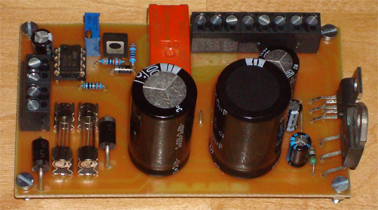
To run the Alpha Centauri you need additional a delay circuit for the main supply. This circuit contains an additional regulation circuit that delivers a stable 6,3V voltage for the tube heaters.
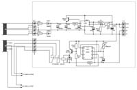
circuit

The core of this circuit is the adjustable voltage and current regulator L200. In order to increase the internal current limit of 2 Ampere of the L200 I used a BD250 for delivering a higher output current. When a voltage drop of 0,6 Volt on R901 is reached, T901 beginns to supply the additional current for the output. The output voltage is adjusted by R904. R902 and C904 determine the steepness of the slew rate after power on.
The delay circuit uses the universal timer IC NE555C. The delay time is determined by R302 and C302 and can be adjusted to 20 seconds. The delay circuit is supplied by the regulated 6,3V heater voltage. This way you have an additional control for this voltage. If the voltage fails, the main supply voltage is immediately disconnected from the amplifier.
Download the complete set (layout, schematics, partlist, etc. here.

regulated power supply V5.5

regulated power supply add on