How does an electrostatic headphone work?
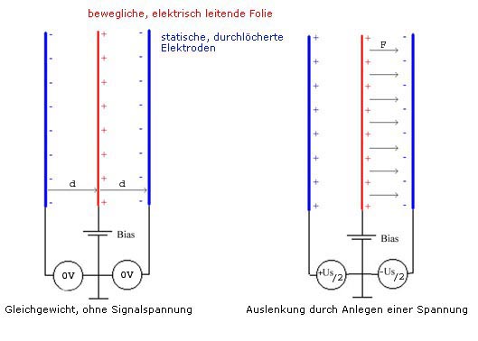
The whole thing bases on the attraktion and rejection of electric charge. Charges with the same polarity are rejecting, charges with different polarity are attracting. An electrostatic transducer has three electrodes. The two outer ones are static, that means fixed, the third, middle is free in movement. Due to the outer electrodes, the middle electrode is charged positive (BIAS). So without any signal voltage the middle electrode is idle, because it is attracted from both sides with exact the same force (left picture). Now if you overlay a signal voltage on the outer negative electrodes (right picture), the middle electrode is moved to the left or right side, depending on the polarity and amount of the signal voltage.
The advantage of such a transducer: The moving force acts homogeneous over the complete diaphragm and not from one point in the middle of the membrane like a dynamic transducer works. Partial vibrations are not generated, that means the transducer works with low distortion. Using a very thin diaphragm there are only very little masses moved, and that leads to an excellent reproduction of impulses.
But now lets look a little bit closer on the relations, shown in the simplified picture above. The diaphragm means a capacitor, related on the two static electrodes that can be calculated as follows:
Depending from the position of the diaphragm the effective capacity will increase when the diaphragm is moved towards one of the electrodes. The effective capacity can be a multiple of the quiescent capacity when the diaphragm aproaches very close to one of the electrodes. Because of the relation
Q=CU
a current will flow from or to the diaphragm during movement. Interesting to see are the forces that act on the diaphragm. They can be calculated as follows:
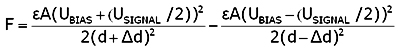 |
You will realize that there is no linear relation between force and change of distance of the diaphragm. The reason for this nonlinearity is the flow of charge carrier during change of capacity. So this is the reason why this concept is not practicable for transducers with large amplitudes.
It will look completely different if you place a high impedance resistor in the circuit of the diaphragm. It will surpess the change of charge carrier during capacity change when the diaphragm is moved, and that means:
Q = CONSTANT
The voltage between stator and diaphragm now changes as follows:
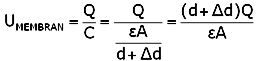 |
The voltage of the diaphragm now changes proportional to the distance and that means a constant electric field strength, independent from the amplitude of the diaphragm.
 |
If you now calculate the force, acting on the diaphragm you will receive a value that is proportional to the signal voltage and depends no longer from the distance of the diaphragm.
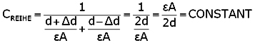
The relations of the capacities have also changed basicly. The effective capacity has changed from parallel to serial and is now constant.
 |
An other advantage of this concept is the reduced risk of collapse that can happen at large amplitudes when the diaphragm approaches to near to the stators. With a constant electric field strength the voltage is proportional to the distance and will be zero when the diaphragm drops the stator.
This concept is nowadays applied to all high end electrostatic transducers both loudspeakers and headphones. With such linear relations it is possible to receive distortion levels far under 1%.
used symbols
|