AC-Tubeamp Capella
circuit
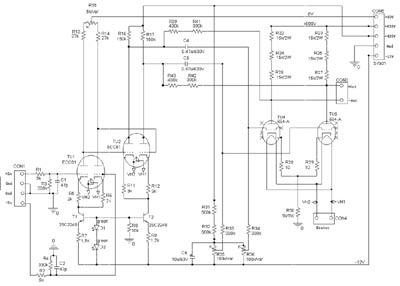
AC-Tubeamp one chanel
My concept of a balanced dc-coupled class-A amplifier I used up to now I did not keep entirely for the benefit of a straightforward effort. To build a dc-coupled amplifier in tube topology means an enhanced effort and it is questionable if this enhanced effort will have negative effect on the sound quality. This amplifier gets by on only two coupling condensators in the signal path, and they are again integrated in the feedback loop of the output stage. In the periphery are two transistors to implement two current sources but they do not touch the audio signal.
The input signal meets the input differential amplifier TU1. The gain of this stage is defined by the quotient of 30K/2K, reduced to 10 by the low transconductance of the tube. The pot R15 is used to minimize distortion, read more below. The signal is taken directly from the anode of TU1 and meets the input of the next differential amplifier TU2. The gain of this stage is 100k/3K, reduced by the low transconductance of the Tube TU2 to 20 (R16/R17 must be seen as a parallel circuit with R33/R34, then results in 100K). With a load of 45K for the output tubes you have a gain of about 14 for the last stage, reduced by the local feedback to 8. The BIAS current for the output tubes is 8mA. Remember that you are working with unbalanced power supply, that means at CON3 a BIAS voltage of Ub/2. To prevent oszillation, I did not use an overall feedback. Instead I used local feedback for every stage, current feedback for the first two stages and a voltage feedback for the output stage. For the output stage a current feedback is not practicable because the output impedance of the tube would become very high. Instead a voltage feedback (R39 to R42) reduces the output resistance and also distortion and therefor it is much more practicable for a output stage. With the pots R35/R36 you can adjust the operating point to Ub/2 separate for +out and -out. For maximum performance, I recommend to keep the conditions for the supply voltages as exact as possible. You can use the power supply for the RTR400 or better my regulated power supply. In both cases the 150 Volt auxiliary voltag must be reduces to 80 Volt by replacing the 150 volt zenderdiode with a ZPD75.
The output stage has a operating point of 460 Volt, so you have to lift up the BIAS-Voltage on the power supply from 580 to 640 Volt. To do this, replace D501 by a 180 Volt type on the RTR400 power supply or if you use my regulatetd power supply replace R601 by a 180 Volt type.
The amplifier is designed for 50K input potentiometers. If you don't use them, you have to replace the 330K resistors R3 and R4 by 50K resistors. The static differential input voltage of TU1 can so be led to ground. Otherwise the differential voltage would unbalance the input section of the amplifier, increase distortion and reduce the maximum output voltage.
Layout
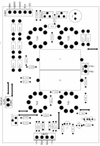
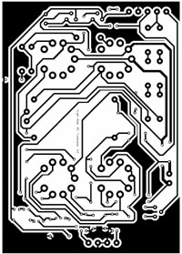
dimension: 95 x 135 mm
Partlist you find here.
Here my designs for front- and backplane for the Frontplatten-Designer from schaeffer-apparatebau. The enclosure comes from www.modushop.biz in italy.
starting up
WARNING!!!
Remember that you are handling with high voltages that can be dangerous to life. So if you are working on powerd on devices use only one hand in order to prevent electrical shock.
If the amplifier is connected to the power supply you can begin with adjustment. First put all pots to center position. Connect the input to ground and adjust the output voltage at +Out using R35 and -Out using R36 to +460 Volt. You have to repeat the adjustment until the voltages fit, because the output voltages are interacting a little bit.
You can use R17 to adjust the distortion of the amplifier to a minimum. If you use well matched tubes, R17 shoud be in center position after adjustment, and the voltages at R16 and R17 should be equal. If you don't have any distortion meter use these voltages for orientation. My experience says that distortion is at minimum when these voltages are nearly equal.
The amplifier is now adjusted and ready for operation. Remember that BIAS tends to drift away if using virgin tubes, so adjust the amplifier again after 10 hours ontime.
result
With the recommended supply voltage of 800 Volt the amplifier can output 450 Volt eff (=1250Volt Vss from stator to stator) before clipping. The distortion is untypical low for a tubeamp without overall feedback, in the condition that you use matched tubes. If you use unmatched tubes distortion can increase up to four times higher. The 6S4-A can withstand 2KV peaks and has a maximum power consumption of 8,5W so it will operate within proper limits. The power consumption of the amplifier is 70 Watt. It can drive all STAX Pro headphones (580Volt BIAS), if you reduce BIAS to 280Volt it can drive all STAX headphones. Certainly you can drive other electrostatic headphones like KOSS, Jecklin Float, Sennheiser, etc, just fit the BIAS to the desired value.
The sound does not get out of line and differs from my other designs only marginal, the highend is a little decenter. All in all a fine resolution with powerful, structured basses. The amplifier is equiped as follow: TU1 from Siemens, TU2 from Tungsram, the endtubes from RCA. The coupling condensators are MKP-QS condensators from AUDYN-CAP, to order from schuro.
measurement results (supply voltage 800Volt, all voltages RMS)
distortion level vs. output voltage f=1KHz:
100Volt: 0,07%
200Volt: 0.2%
300Volt: 0,4%
400Volt: 0,8%
450Volt: 1,5%
distortion level vs. frequency:
Uout = 100Volt:
100Hz: 0,08%
1KHz: 0,07%
10KHz: 0,08%
Uout = 200Volt:
100Hz: 0,15%
1KHz: 0,2%
10KHz: 0,16%
chanel seperation vs. frequency (Uout = 100Volt):
100Hz: 79dB
1KHz: 59dB
10KHz: 40dB
signal-to-noise ratio: 90dB
output impedance at 1KHz: 10KOhm
frequency response (-3dB): 0,3 - 40000 Hz